BSpline BRep Geometry
BSpline BRep 3D geometry is the geometry type created during import of solids via
STEP or IGES formats. It is the most flexible parametric representation of
objects with surfaces.
BSpline BRep entities can also be created programmatically using
IStdShape_DG
interface, IObjectGenerator_DG.Create*()
or interactively using Model Explorer. BSpline BRep objects are also created during numerous operations.
IBRepBuilder_DG
interface allows building BSpline BRep objects from the ground up by defining
geometry of its vertices, edges and faces. See implementation of ShapeBuilder class
in Shape Explorer sample for
an example.
BRep Structure
BSpline BRep Geometry is represented by shape object. Most of shapes have sub shapes. In software terms
shape is a base class for more specific classes: Vertex, edge, face, etc.
A shape representing BSpline BRep object is organised hierarchically: Most often the top shape is a solid.
Sometimes, for example after a Boolean operation, a solid
becomes divided in two or more pieces. In this case the top shape used in the geometry becomes a Compound.
Generally, compound is a set of shapes of any type.
A linked piece of surface of a solid is called shell.
Shells are sets of faces (Details), joined together
by edges, which often constitute a closed surface. Most often a solid has a single (external) shell.
Surfaces of internal cavities are called inner shells
Face is a smooth (not necessarily flat) piece of surface with several edges.
For an example a rectangle in 3D is normally represented by a flat face with four edges. Faces are sub shapes of
shells.
An edge can be either straight or curved, but always smooth curve with two ends.
Ends of an edge may coincide, in which case the curve is closed.
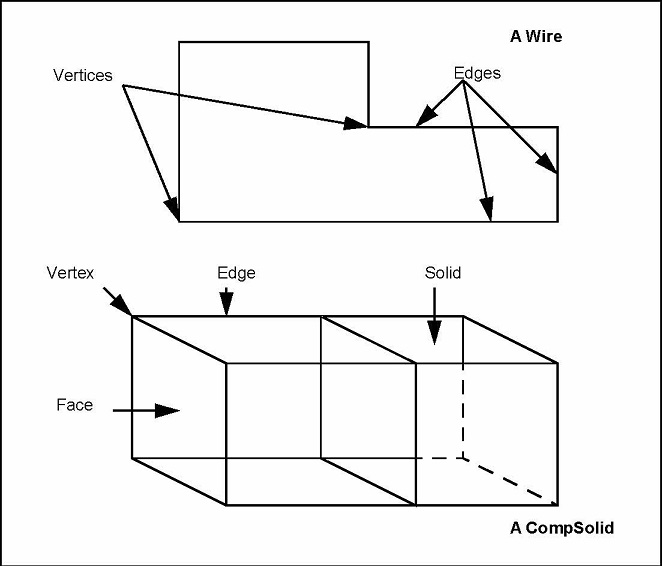
A linked sequence of edges is called a wire. Wires are sub shapes of
faces. Edges are sub shapes of wires.
A vertex, which represents a point with some other non-geometrical additional
information, is the lowest-level sub shape. Ends of edges are vertices. Corners
of a patch are also vertices.
Vertices are shared by adjacent edges and faces.
Vertices, edges and faces are called primitive shapes of dimension 0, 1 and 2 respectively.
More precisely, dimension of a shape is the number of different directions a point can move inside the shape
Solid is a shape represented by a single closed shell
Composite solid consist of one or more solids in which some faces may be shared
by adjacent solids (solids with dividing walls inside)
A Compound shape consists of several grouped, but not necessarily joined,
shapes of different types like solids and edges
A box, for an example, is a solid with a single shell, six faces, six wires, twelve edges, and eight vertices
See also: Shape Explorer Sample
BSpline Geometry
The BRep structure above defines the way shapes are assembled into the final object. To describe
internal geometry of a simplest shape (edge or face) another layer of software is needed. This is
what BSpline Geometry is. BSpline Geometry of a face, for example is a set of equations and other data
which defines the smooth surface of the face.
For edges such geometry is described by curves
More details: BSpline Geometry
|